The SOI Hardware
The SOI CCDs
The SOAR Optical Imager (SOI) features two 2048 (serial or pixels/row) x 4096 (parallel or pixels/column) 15 micron per pixel CCDs arranged as a 4096 x 4096 pixel detector. The CCDs are read out through two amplifiers per chip simultaneously using an SDSU-2 Leach controller. The gap between the CCDs is kept to about 102 pixels in the row direction (see Figure 2 showing an image labeled with chip numbers). We have populated the SOI with thinned, back illuminated E2V CCDs. These chips have only minor flaws which have little effect on their scientific performance.

Figure 2: A flat-field (R band) map of the SOI CCDs with their FITS extensions (im1, im2, im3, and im4) labeled accordingly.
Figure 3 shows the average QE of the SOI CCDs.
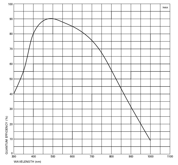
Figure 3: The average E2V CCD QEs.
The Dewar
The SOI dewar contains a highly polished aluminum vessel (11.6 liters) that can be filled with LN2 to 50% capacity via an axial tube and a hold time of 30+ hours. The LN2 can is connected to the CCD mount by a copper braid which has had its thermal resistance optimized. The CCD mount is a kinematic design, with a frame coupled to the dewar front face by G-10 stand-offs. The frame in turn carries the CCD mount and the heater, which is servoed to keep the CCD at a constant temperature to within 0.2 degrees C. The SOI dewar is the smaller blue cylinder on the right-hand side of Figure 4. It is filled by an observing technician at the start of each night.
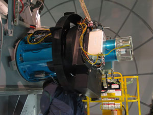
Figure 4: The SOI system mounted on one of the bent-Casseagrain foci of the SOAR Telescope. The dewar containing the 2 CCDs is the smaller blue cylinder located on the right. The SDSU Leach controller is the silver boxr located in front of the dewar.
The Leach Controllers
The two CCDs are read out by an SDSU-3 Leach controller (see Figure 4), connected to a PC running GNU/Linux through a PCI board in a PCI-GNU/Linux-LabVIEW environment. The read-out time using two amplifiers per CCD is 20 seconds in unbinned mode with a 4.4e read noise. Other modes of operation are given in the SOI Overview document at the beginning of this manual. Data values are stored as 16-bit unsigned integers.
The CCD Shutter
The shutter is a single blade "focal plane" type driven by a dc servomotor via a cogged belt. It is low profile (4.7mm) and high performance. Minimum exposure time is less than 200 msec and repeatability below 0.5 msec. The drive profile is trapezoidal. The shutter has been subject to extensive lifetime tests without degradation.
The Filter Wheels
Filters are mounted in two filter cartrides each with space for 4 filters, plus one blank position, so that up to 8 filters can be installed in the instrument at any time. Although the cartridges were designed to be easily removeable, the process of changing them out still requires at least 30 minutes, and we currently have no spare cartridges. Thus it is strongly recommended that users design their programs to avoid filter changes during the night. Filters may be up to 100mm square and up to 10mm thick. Smaller filters may be accommodated with special adapters but must be at least 64mm square to avoid vignetting. To see the list of the currently available filters, together with transmission curves, click HERE. Filters from the CTIO filter list are also available.
The Tip-tilt Guider
The tip-tilt guider consists of a probe containing a miniature (10 mm side) right angled prism which diverts a small portion of the input beam to a second prism, where the beam relay optics send it to the tip-tilt guider detector. The prism size and probe arm cross-section are small (the latter has a cross-section of only 5 mm) because the prism and probe arm may need to occult the science beam if the guide star is desired, or can only be found, close to the field center. The probe assembly is mounted on a Parker-Daedalus XY-stage, with 0.5 micron resolution. It is also possible to fine-tune the focus independently from the telescope focus. The detector system is a thinned, quad-readout Marconi CCD-39 that is thermoelectrically cooled and operated by an SDSU Leach controller in frame-tansfer mode.
The Rotator and Cable-wrap
The rotator mechanism is driven by a servo motor, directly coupled to a Harmonic Drive gear reduction. This turns a bronze friction wheel against a larger steel wheel which houses a 4-point ball bearing that is attached to the rotating part of the instrument. Position sensing is achieved by a tape encoder located inside the bearing housing. It has a resolution of 0.16 arcsec, more than needed. The rotator has a maximum rotation speed of 0.48 degrees per second and has redundant limit switches for safety. The cable-wrap consists of a IGUS energy chain system, specially manufactured for this application. It is lubricated with Teflon to reduce friction.
The Focal Reducer Optics
All elements of the focal reducer are held in individual cells. The triplet is held by 8 preloaded spring elements with hard points only in the axial direction. The compression of the spring elements was calculated to achieve an acceptable centering. The other two cells are of the "finger" type commonly used in CTIO instruments.
The Atmospheric Dispersion Corrector
The atmospheric dispersion corrector (ADC) incorporated into the SOI is a two-prism linear "trombone-like" design, such as that adopted for the FORS instrument on the VLT. This design is particularly well suited for and alt-azimuth telescope as the angle between the image plane (i.e., the telescope altitude plane) and the atmospheric dispersion axis remains constant for all zenith distances, thus avoiding the need for prism rotation. This holds for any instrument, as is the SOI, mounted on the telescope tube. Our ADC consists of a pair of fused silica prisms with the same apec angle and a constant 180 degree orientation offset. The forward prism corrects for atmospheric dispersion by moving longitudinally in the beam and the fixed prism corrects for the image plane tilt. An image shift occurs depending on the prism separation that can be compensated for by the telescope pointing model.
At present the ADC is not used during SOI observations.
Updated on May 27, 2021, 4:05 am